Thursday 12 March 2020

PiWars 2020: Collision warning!

A major cause of the disasters that International Rescue get called out to are caused by collisions. Whether its a fuel tanker hitting a rock slide, or an experimental jet crashing into the ground, it usually results in a large explosion (regardless of how explosive the objects involved actually are). So when running autonomously how do we avoid Thunderbird 2 running into things? (Obviously in a manually controlled environment nothing is going to stop us crashing !).
Boom!
The answer is to add sensors that are capable of detecting how close it is to an object. Generally these are referred to as 'distance sensors', which come in a variety of form factors and types, and tend to work by 'firing' something outwards, waiting for it to bounce off a surface, return to the sensor and then measuring the travel time to determine how far away it is. This process is similar to working out how far away an object is by making a loud sound and listening for the echo.

Popular choices are ultrasonic sensors, which uses sound waves to determine distance, Time-of-Flight sensors, which use lasers, and some camera based systems (which use magic... or possibly maths).

Sensors!

My requirements for Thunderbird 2 are that the distance sensors are small enough to be hidden behind the 'air intakes' for the jet engines, and that multiple sensors can be used at the same time. This rules out the ultra sonic sensors, as the sound waves they fire out could get picked up by multiple sensors, giving an invalid reading, as well as the camera based systems. Instead I'll be using several VL53L1X Time-of-Flight sensors.

There are a number of different models of the VL53L1X sensors, all built around the same core module, and which one you select depends on your requirements. In this case I wanted a module that had a small physical size, and exposed all the control pins.

The VL53L1X  sensor communicate via I2C. This is a protocol that allows multiple devices to be connected to the same physical bus (i.e. The communication pins are all connected together), which greatly simplifies the wiring as it allows you to chain multiple I2C devices together instead of needing each one to be directly connected to the Raspberry Pi.

All connected to the same I2C bus.

To talk to an I2C device you need to know its address, similar to how you specify a house on a street by its number. According to the VL53L1X  datasheet its default address is 0x52 (82 in decimal), which we use to make sure our post (the commands) reach the correct house.

Unfortunately if all the sensors share the same I2C address then the postman is going to get very confused about where these messages should be delivered to. Luckily this particular sensor allows its I2C address to be changed, by sending a command. This could be considered a bit of a chicken or the egg issue, how do you tell a sensor to changes its address when you can't send a message until the addresses have been changed?

Luckily the designers of the VL53L1X  sensor did consider this and provide an extra PIN, called XSHUT, that can be connected to a GPIO which turns on or off the sensor. Allowing us to turn on one at a time, reconfigure it,s address and move to the next. Now not all ToF sensor models expose this PIN, so this is another item we need to check for,

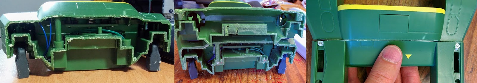
After a bit of searching around, and measuring of space, I found one produced by Pololu that looked like it would meet all the criteria. Purchasing one to double check the fit, always a sensible idea before you commit, before getting all 4.
It fits!
I initially connected the sensors via jumpers leads, but quickly decided this was too bulky and inflexible to fit inside the case, especially as I had four to connect up! Taking advantage of the ability to chain I2C devices I switched to ribbon cable, a thinner and more flexible cable, along with some 1x7 connectors. This worked at first, but when I came to chain two I managed to get the cable a little twisted, mis-wired the connector, and managed to produce a 'burning' smell from a sensor... Ooops!
To avoid this in future I purchased some multi coloured ribbon cable, making it much easier to work out where each cable goes (Even later on I found the roll of rainbow colour ribbon cable I'd bought a year or two earlier...
Two sensors in a nice, neat, rainbow coloured line.
Repeating the setup on the other side I know have a full set of four sensors, two pointing forwards and one pointing to either side. This allows Thunderbird 2 to detect walls in front, and either side, in theory allowing it to safely navigate through the maze and the lava palava course.

Now all it needs is someway of actually moving! Which I plan on covering next time!

Leo

Thursday 20 February 2020

PiWars 2020: Brains

Mr X and Mr Hackenbacker
With the chassis cut to size its time to start thinking about brains. No, neither Mr X. or Mr Hackenbacker, nor the type of brains that the targets in the Zombie Apocalypse challenge would be interested in snacking on.  

Instead the brains of a PiWars robot has to be a Raspberry Pi, and in this case a Raspberry Pi 3A. Its combination of smaller size, whilst maintaining the power of its full sized brethren, makes it a go-to solution for many of the PiWars competitors.

Why not a shiny new Raspberry Pi 4 I hear you ask? Well for one a full sized Raspberry Pi takes up too much space in the cockpit, it would fit but then the battery wouldn't. Its also unlikely that any processing I need to do for the challenges would noticeably benefit from the increased performance, whereas the increased power draw, and heat produced, could have a detrimental affect on the robot. The additional i2c buses might be of use, but unless a 4A is suddenly announced I'll be sticking with the 3A.
Too big on the left, fits on the right (Battery hidden out of sight)
Now a brain is of limited use without inputs to process and outputs to control. For the manual challenges the input will be a Bluetooth connected PS4 controller, an upgrade for this year as my, more traditional, PS3 controllers are starting to show their age with the joysticks being a little unreliable.

For the autonomous challenges the main inputs will be a Raspberry Pi camera, and a set of 4 VL53L1X Time of Flight (ToF) sensors positioned around Thunderbird 2. The camera, when combined with opencv, will be used to take pictures and perform either object, or more simply, colour recognition to aid in navigation. The ToF sensors, which work by firing lasers, will be used to detect how close Thunderbird 2 is to a wall or object.

RPi Camera and ToF sensor 
The camera will be positioned above the cockpit so it can look ahead, but might get moved to more suitable locations as required for the various challenges. The ToF sensors will be aimed forwards and to the sides, which I'm hoping will help in navigating the 'Escape route' and 'Lava Palava' courses, allowing Thunderbird 2 to maintain a set distance away from a wall, and to detect when its about to drive into one.

The obvious output will be the motors that drive Thunderbird 2 around, with the less obvious being the gun for Zombie Apocalypse and, if I manage to get to it in time, a mechanism for capturing barrels in 'Eco Disaster'. I also hope to have an actual GUI this year that will be displayed on a wrist mounted Raspberry Pi (Fitting in with the newer 'Thunderbirds Are Go' way of remotely controlling one of the Thunderbirds).
Motors!
Connecting everything up is liable to be a python program or two, hopefully reusing some of last year's code, but most likely a whole bunch of new stuff. I'm currently feeling drawn to having dedicated python processes to monitor different aspects, say a dedicated process for dealing with the ToF sensors, feeding the results to the main controlling application that then decides if its interested in the information or not.

Of course I'll be going into more detail on these items in future blog postings, unless I completely run out of time and abandon them!

Leo

Thursday 23 January 2020

PiWars 2020: Making the cut

Before I can best plan out how to convert the Thunderbird 2 toy into a successful PiWars competing robot I need to open it up and see what I'm working with. Happily the toy opens up quite nicely, just a case of removing every screw you can see on the underside of the chassis and popping the two halves apart. Most of the internal items also unscrew easily with the notable exception of the tail. Whilst it looks to just be held in place by 2 screws either side, it appears that the manufacturer also glued it into place for extra strength, and by the time I realised this I'd snapped off one of the supports...

Opening up the chassis
The pod themselves open up nicely too, just remove a couple of screws and pop it apart. Remove a few more screws and the launching mechanism for Thunderbird 4 comes out as well.
And opening up a Pod.

In terms of usable space the main two areas of interest are the inside of the cockpit and pod. These can both house a full size Raspberry Pi, barely in the case of the cockpit, and with room to spare in the pod. As my plans are to swap out the pods for different challenges this means the controlling Raspberry Pi must be housed in the cockpit (to comply with the rules of PiWars), leaving the Pod to house the motors and any additional hardware required to complete the challenges.
Tight squeeze on the left, roomy on the right.
With the toy opened up what's the next step? Well, those who read through my PiWars application details in the last posting may have spotted the line at the end stating that the Thunderbird 2 model is too long and needs cutting down to size...
So the length limit is 300mm...
Last year, in PiWars 2019, I made an effort to keep Wall-E looking like the original toy, which turned out to be a challenging task, but at the end I was happy with my decision (Apart from maybe the gear box failures!). With Thunderbird 2 that just isn't going to be an option, so with the cockpit ear marked for holding a Raspberry Pi then its the tail that will have to be chopped off. I had hoped to keep the battery compartment, which is towards the rear, but the vast majority of that also fell outside the 300mm length limit.

Big and cutty
But how to remove it? As I have recently started attending a MakerLab, I've gained access to a variety of big cutting tools  and I decided to give one of those a go. After all a mains powered, table mounted bandsaw thingie should have no trouble cutting through toy grade plastic...
Well technically it had little trouble cutting through Thunderbird 2, however it generated so much heat that the plastic melted back together again afterwards! Requiring a bit of wiggling and hacking at until the tail could be broken away, plus a bunch of post processing to tidy up the cut.
Transitioning from scruffy to nice and smooth.
The tail section has quite a lot of weight to it, so now its been removed Thunderbird 2 gets a little front heavy, and will get even more so when the battery and Raspberry Pi are installed. So the plan is to install counter weights to balance things out. Where I can I hope to reconnect the tail section as an 'attachment' for some of the challenges, and Mike has helpfully confirmed its okay for the attachment section to be on the back. Hopefully a few magnets will be strong enough to hold it in place, whilst also allowing for easy removal. However this isn't strictly necessary and will be in the 'nice to have' list of features.
Thunderbird 2 - Compact edition
With the chassis cut down to size the next step will be installing the brains!

Leo

Tuesday 14 January 2020

PiWars 2020 : Calling International Rescue!

Wall-E from PiWars 2019
Its a New Year and a new PiWars. PiWars 2020 is coming in March and once again I've managed to get selected as a competitor! After the success of last years' Space themed event (My entry being the lovable robot Wall-E) Mike and Tim decided to repeat it for 2020, this time going for a 'disaster' theme, either natural or man-made, with a leaning towards disaster related movies.

I can come up with a lot of ideas for disaster themed robots, one with a volcano on it, or a bursting dam (pumping water back behind the dam so it can burst again), or just an alien robot come down to Earth to destroy and invade.

All fun projects, but there was a toy conversion I've had on the back burner for a while and this seemed an appropriate time to use it. After checking that 'rescue' themed robots were included in the 'disaster' category I submitted my application for Thunderbird 2. After all, where there's a disaster International Rescue won't be far behind!

Thunderbird 2!

As this is the 5th time I've entered PIWars you'd think I'd have a good handle on what to do. However, in reality, I'm still making a lot of this stuff up as I go along. But.... as long as I write down my ideas it becomes 'planning' which is a much more responsible sounding word.

So what sort of ideas did I write down? Mmmm rather a lot!  Here's a copy of my application (Might also be of interest to anyone wondering what to put in a future Pi Wars application)

Robot will be built around the Thunderbird 2 Supersize toy (From 2015).

The main chassis will contain a RPi 3A+ as the main controller, as well as a battery, camera and multiple ToF sensors (One under each air intake on the front, plus one on either side). Other sensors/components may be added as the build progresses..

Actual propulsion will be contained inside the Pod (As this is the only section that touches the ground) and it is planned that the Pod will be swapped out for the various challenges. Initially the RPi 3A+ will be connected physically to the motor driver inside the Pod (e.g. via i2c), but if development goes well this will change to a wireless communication (NFC, bluetooth, WiFi, something else?). Ideally I’d want to get to the point where the Pod can just be swapped out, the RPi 3A+ automatically detects this (via NFC) and the software updates as appropriate.


Current plans for Pods are

Pod 1: This will be the standard Pod that will be used in the majority of challenges. Current plan is that it’ll contain a twin set of tracks, that come through the floor of the pod, which also includes some limited vertical movement. So for the obstacle course the ‘bottom’ of TB2 can be raised by 1 or 2 cms to clear obstacles, ramps etc. It may also contain a line following sensor for the ‘Lava palaver’ challenge, if that doesn’t end up being carried in the main chassis.

Pod 2: This pod will be targeted at the ‘Zombie Apocalypse’ challenge. It will have a much simpler motor mechanism to free up space inside the pod (prob. Just a couple of wheels to allow movement over flat terrain). This extra space will be used to house a rotating turret to fire foam darts at the targets. Expectations are that this will rotate left and right to allow more precise targeting, compared to moving the entire robot, as well as some limited up and down movement to fire up and down. A laser will be installed to improve aiming.

Pod 3: This pod will be targeted at the ‘Eco-Disaster’ challenge. Again this will have a simpler motor mechanism, probably a match for Pod 2, but this time the space will contain a gripper arm that will be deployed out the front of the Pod (The main TB2 chassis will be raised to accommodate this). This will have to be fairly long, as TB2’s nose can’t clear the barrel height, and will be used to grip and capture the barrels. Holding them in place as they are delivered to the target areas. Expectation is to use an IR beam, or physical button, in the gripper to detect when it should close. As well as a second camera that will be used to verify the colour of the barrel (This will be streamed to the RPI 3A+ over WiFi for processing).

If time permits, and it turns out to be practical, a mask will come out the top of the Pod and hold a third camera that points downwards (With a wide lens) to better detect barrels in all directions, instead of having to rotate around until one crosses the LoS of the front mounted camera (Or this may end up coming out of the top of the TB2 cockpit for ease of connecting up)

This camera mask mechanism may also be used for the ’Minesweeper’ challenge, to detect which square is lit up.

Control will be done via a simple UI accessed via VNC or web page from a wrist mounted device (vaguely matching how remote control of TB2 is done in the newer ‘Thunderbirds Are Go’ series). This is liable to be another RPi with a touch screen display.

Note: As the TB2 model is too long, the engines and tail have been cut off to meet the max length in the rules. Outside of the challenges this will prob. Be attached via magnets for appearances sake.

Will I complete all these tasks? Well I've never managed it before! But only time will tell...

 Leo